Custom BLDC-Controller
Developing our own motor controller
Our platooning demonstrator, of which we already wrote in our previous posts uses small hobby RC cars as the basis for the model cars. Until now we have used the Electronic Speed Controller (ESC) which came with the cars to easily control the motor of the cars. This was very handy, as it used the same interface as a servo motor, which is basically just a PWM signal where the pulse width varies within a certain range to indicate speed and direction of the motor. This made the complex task of controlling a BLDC motor really easy.
Our problem
The problem with this approach is that we don’t get any signal back from the motor or the ESC. Because we needed to know the speed of the car, we decided to tap into the sensor output wire of the motor, which also goes into the ESC. This was a bit hacky but worked for the time. But with this approach we still didn’t have any feedback from the ESC itself, which was a problem in certain circumstances. The ESC has some built-in safety features, for example over current protection in case the motor draws too much current. This is a great feature and avoids damage to the components but is only indicated by a blinking LED on the ESC, which we obviously can’t detect programmatically. Even worse, the ESC needs to be power cycled to clear the error. This was a problem, as after most crashes of the cars you need to reset the ESC to be able to start the car again. That means going to the car, taking of the housing and resetting the ESC. Another problem with those ESCs is the speed control part of their name. Their speed regulation does not work very reliably. Meaning with varying battery voltage the speed of the cars also varied a lot even though the ESC were set to the same speed. This meant that the speed of the cars decreased when the battery drained, which for our use case is not acceptable as we need to hold a steady speed for our platooning showcase. Until now we tried to combat this with a speed regulation in software, which would vary the input to the ESC to account for the decreased battery voltage. But this is not a good approach in the sense of compartmentalization of software and hardware.
Our solution
Because of all these drawbacks of our current solution, we decided to roll our own ESC/motor controller with all the features we needed for our application.
The Idea
To summarize, we wanted our solution to have the following features:
- Control a BLDC motor, optionally also a brushed motor
- Control the speed of the motor on its own in a closed loop style
- Bi-directional communication with the host system, for example via serial interface
- Report the current speed of the motor via this interface
- Report any detected errors via this interface and reset them if possible
- Optionally be able to control the steering servo of the cars as well
The Software
The hardest part of these requirements was the ability to control a BLDC motor. To help with this part we used the excellent library SimpleFOC, which is exactly made for this purpose. It allows to control a BLDC motor in many different ways, controlling the speed, the angle of the motor or the force which the motor uses. It achieves this using a closed loop field oriented control (FOC) approach, meaning it sends out a control signal to the motor and reads back information about the state of the motor via different sensors. These sensors could be rotary encoders, magnetic sensors or, as in our case, hall sensors, which report the current orientation of the motor.
The Hardware
The SimpleFOC library also suggests different ICs to control the motor. The problem we were facing at the time of developing our ESC was the parts shortage due to the COVID-19 pandemic. This meant that most of the ICs that the library was suggesting simple couldn’t be obtained. After a while of searching for alternatives to the suggested ICs we found the Trinamic TMC6140. This IC allows to control any BLDC with the help of 6 external MOSFETs. The 6 inputs of the IC control which output MOSFET is triggered. The IC also has some additional features, such as current measurement or detection of short circuits or under voltage as well as bootstrapping for the high side MOSFETs. Another nice benefit of this IC is that it can be bought as a development board with all the necessary complementary components and all the connections needed for a test setup. This made the first test of the project fast and easy to set up.
For the brain of our ESC, we decided to use a fast and modern STM32 microcontroller, which was partly also because it was available despite the parts shortage. It also needs little additional components and is easy to program with the Arduino framework.
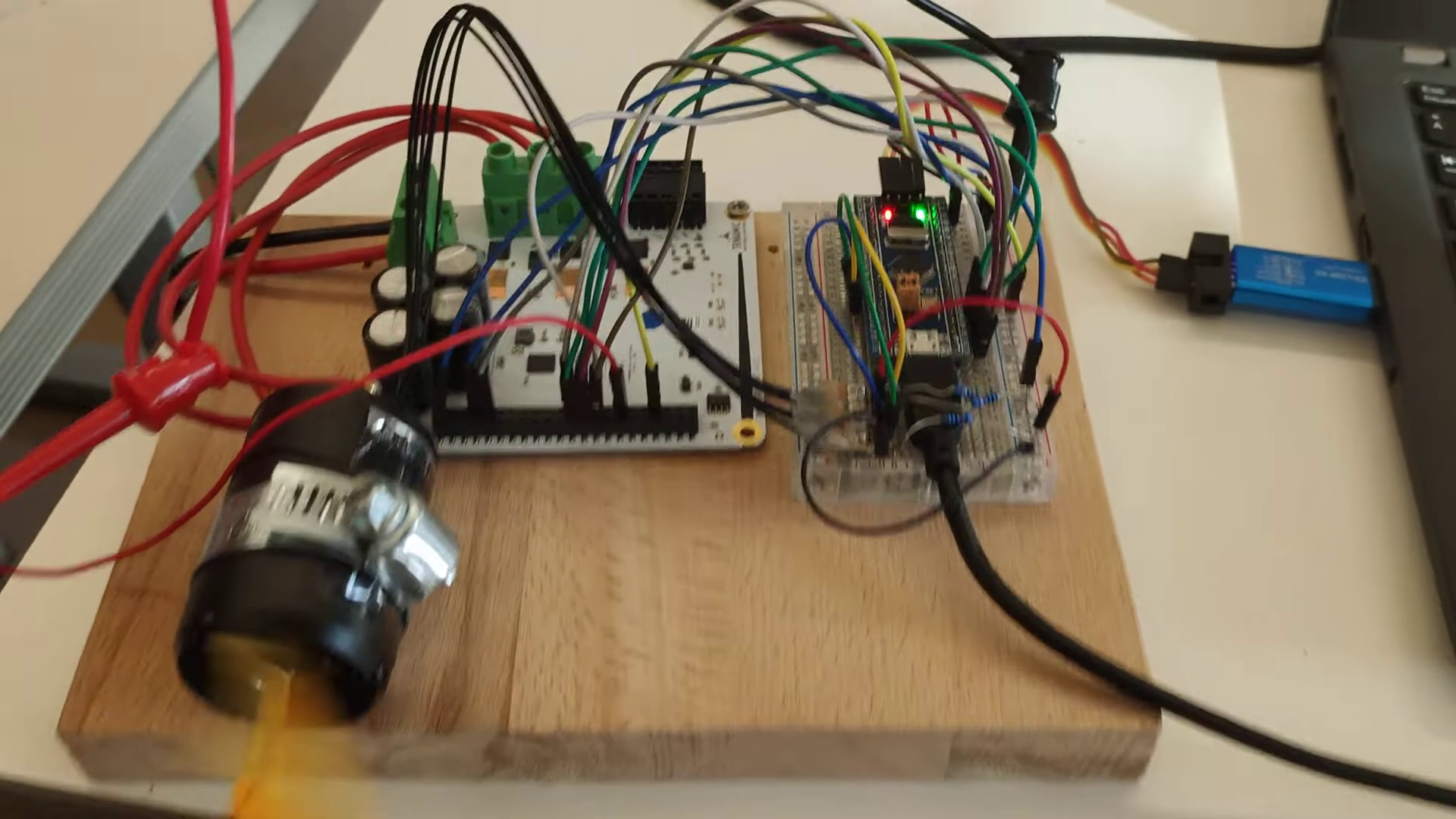
The Process
As a first step, we ordered the TMC6140 development board and an STM32 development board. This allowed us to set up the hardware using breadboards and jumper cables, making it easy to test different configurations and find errors. To control the speed of the servo externally the SimpleFOC library offers a simple and configurable serial interface. Where you can specify the speed of the motor as well as different parameters to influence the behavior of the motor. Having found a working hardware configuration, we moved the whole breadboard assembly onto one of our model cars to see if the motor could also be controlled when it needs to power the car. When this worked, we also added the ability to control the steering servo of the cars with our test setup. This was easy, as there are already premade libraries for the Arduino to control servo motors given a desired angle.
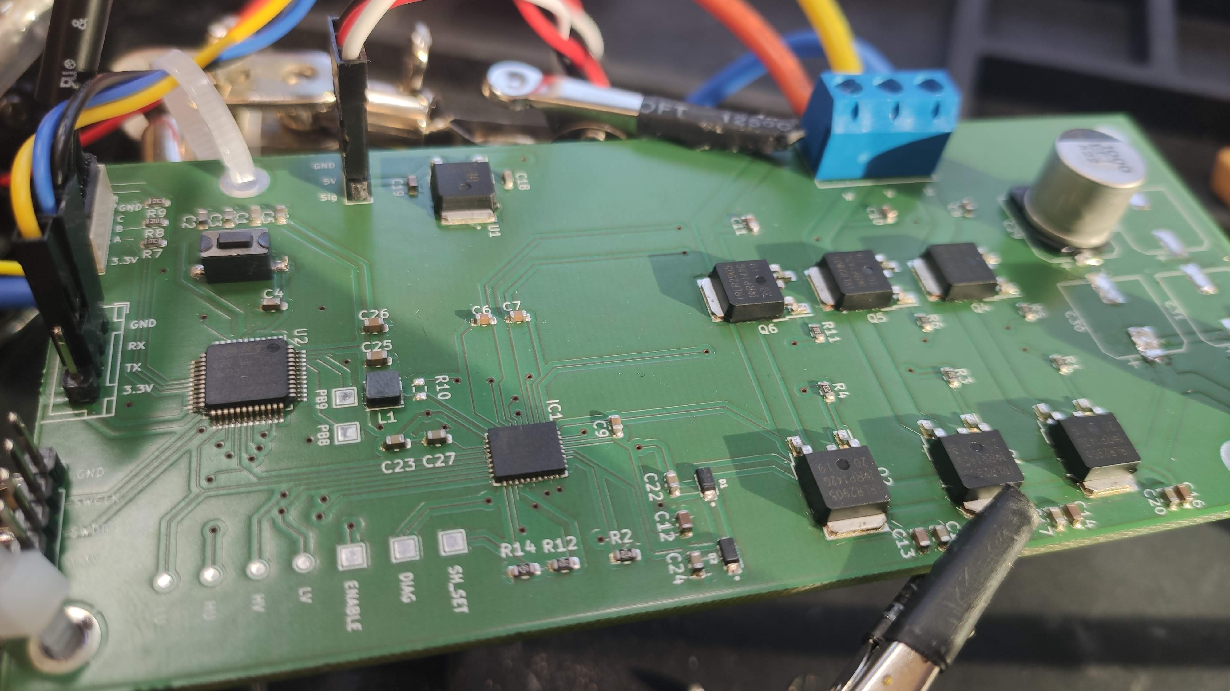
After we verified that the hardware and software work, we needed to move the breadboard setup to an actual PCB. In doing so, we also removed some not-needed components from the TMC6140 and STM32 development boards. As we were unsure if these modifications would work, we decided to first create a test PCB with additional pads for those components and test points for all important signals. We used KiCAD to design our PCB. A great help was the reference design for the TMC6140, provided with the development board and the publicly available reference designs for STM32 applications. The PCBs were manufactured by an external company and assembled in our institute using our own SMD assembly and soldering line.
We then installed the completed PCB on one of our cars and tested the same functionality as before. And everything worked as before, even with the removed components. This showed that our design was correct.
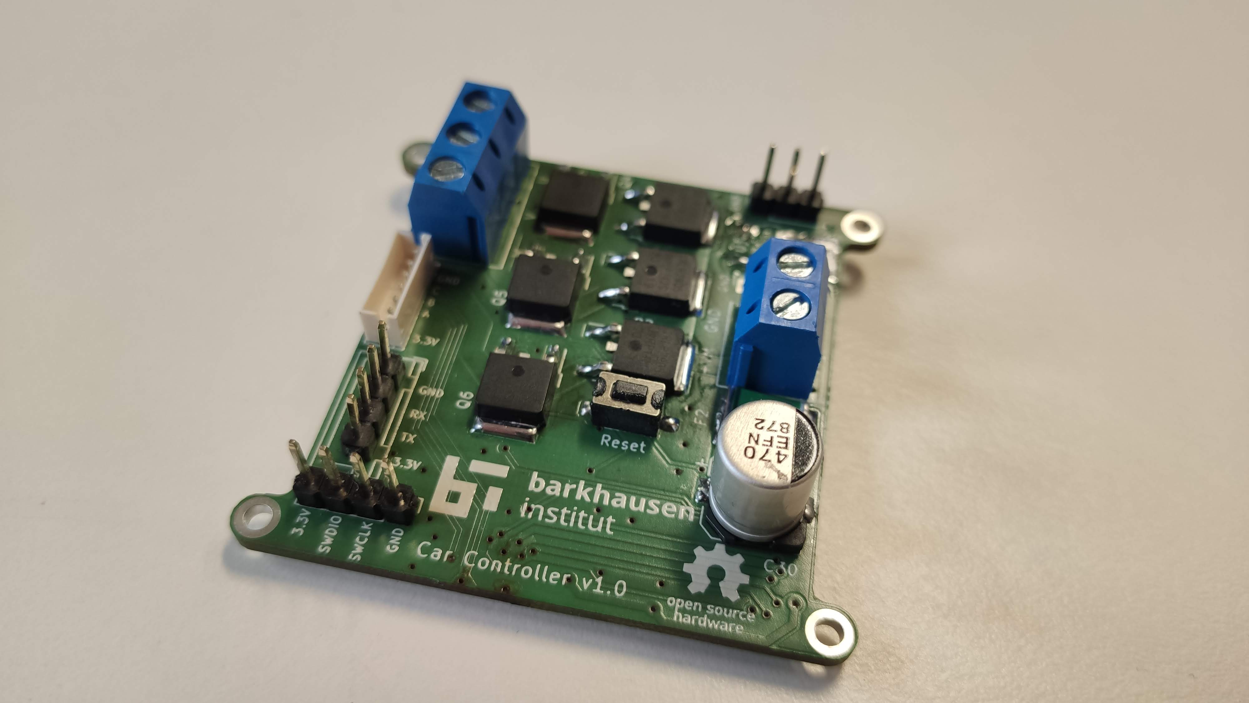
With this knowledge we then could go on and create a smaller PCB as the test PCB was too big to fit comfortably on the cars. So, we removed the unneeded component pads and packed all the remaining components closer together, including on the backside of the PCB. As our current SMD soldering approach only allows soldering single-sided PCB, we could only place the smaller components on one side and only bigger components, which could be soldered by hand on the other.
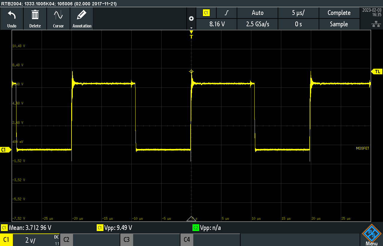
After assembling these final PCBs we could test them again with the cars. At this point we unfortunately noticed, that the controller did not work as expected anymore. As soon, as the required current from the motor exceeded a couple of 100mA the STM would lock up. Even a restart via the reset pin would not help, only after disconnecting and reconnecting the power to the board was the STM responsive again. We took quite some time to figure out what the problem was. We connected the STMs reset line directly to 3.3V, we powered the STM directly from an external known good source, but nothing seemed to help. We then connected a scope to the STMs power rails and noticed very high voltage peaks, even when the STM was powered by an external source. We then figured out, that these voltage spikes were present even between two different ground pads.
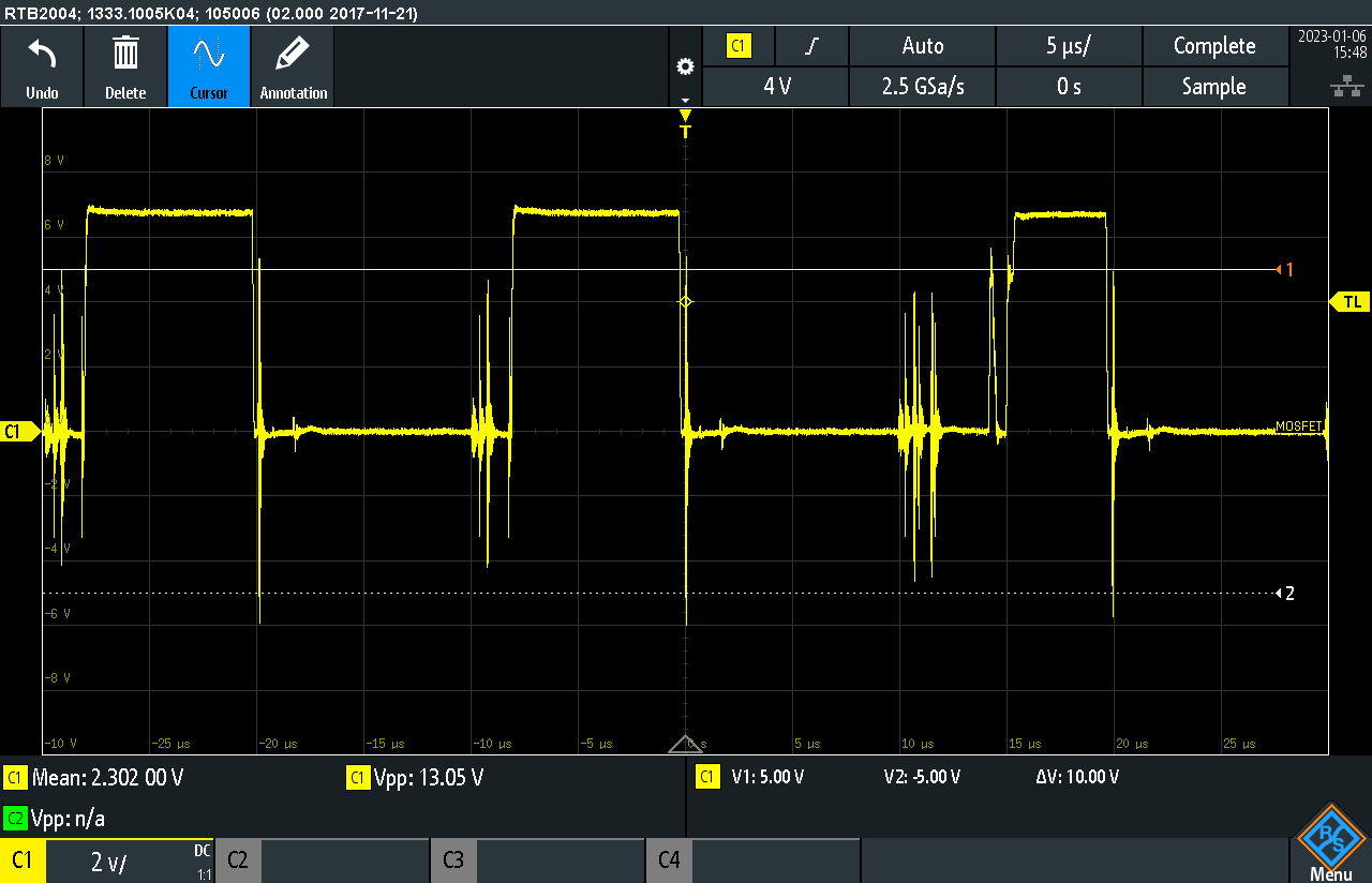 This discovery lead us to the conclusion, that the different ground points are not connected well enough, especially those of the high current components like the MOSFETs. We also took a look at the datasheet of the TMC6140 again which also mentioned the importance of good grounding between it and the MOSFETS. So to test our theory we connected all the relevant ground pins of the MOSFETs, the TMC, the capacitor and the screw terminal together with short runs of cables. This eventually resolved our problem and stopped the STM from locking up.
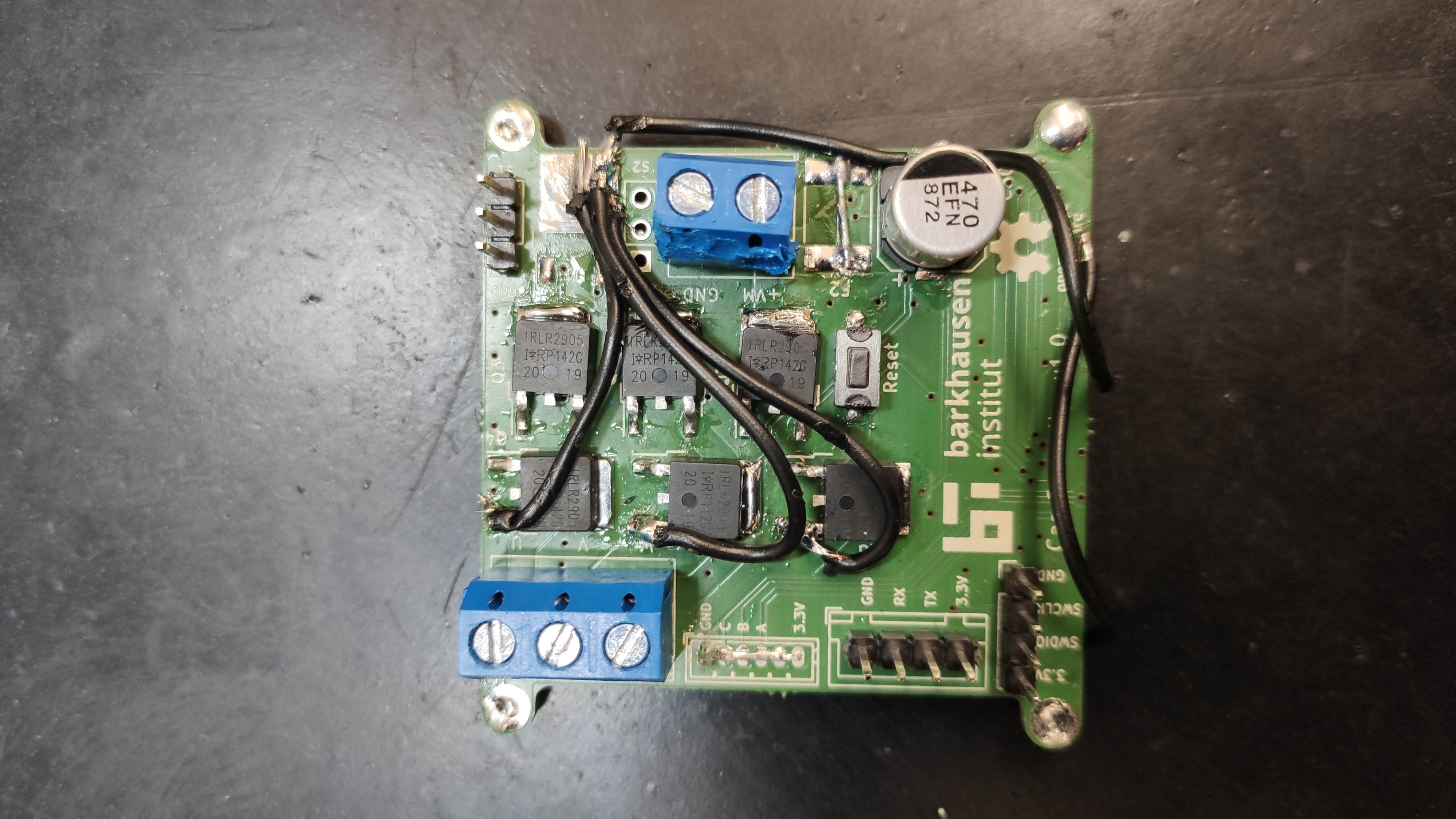
With this new knowledge we now needed to redesign the PCB to account for the better grounding needs. As there was not enough room on both the upper and lower layer on the PCB to make good connections we decided to move to a four layer PCB which allowed us to dedicate a complete layer just to ground. Knowing that all high current paths need to have a low resistance we also doubled up the 12V tracks and the tracks from the MOSFETs to the output terminals using the additional layer. To ensure a good connection between the different layers we added many vias on the high current paths.
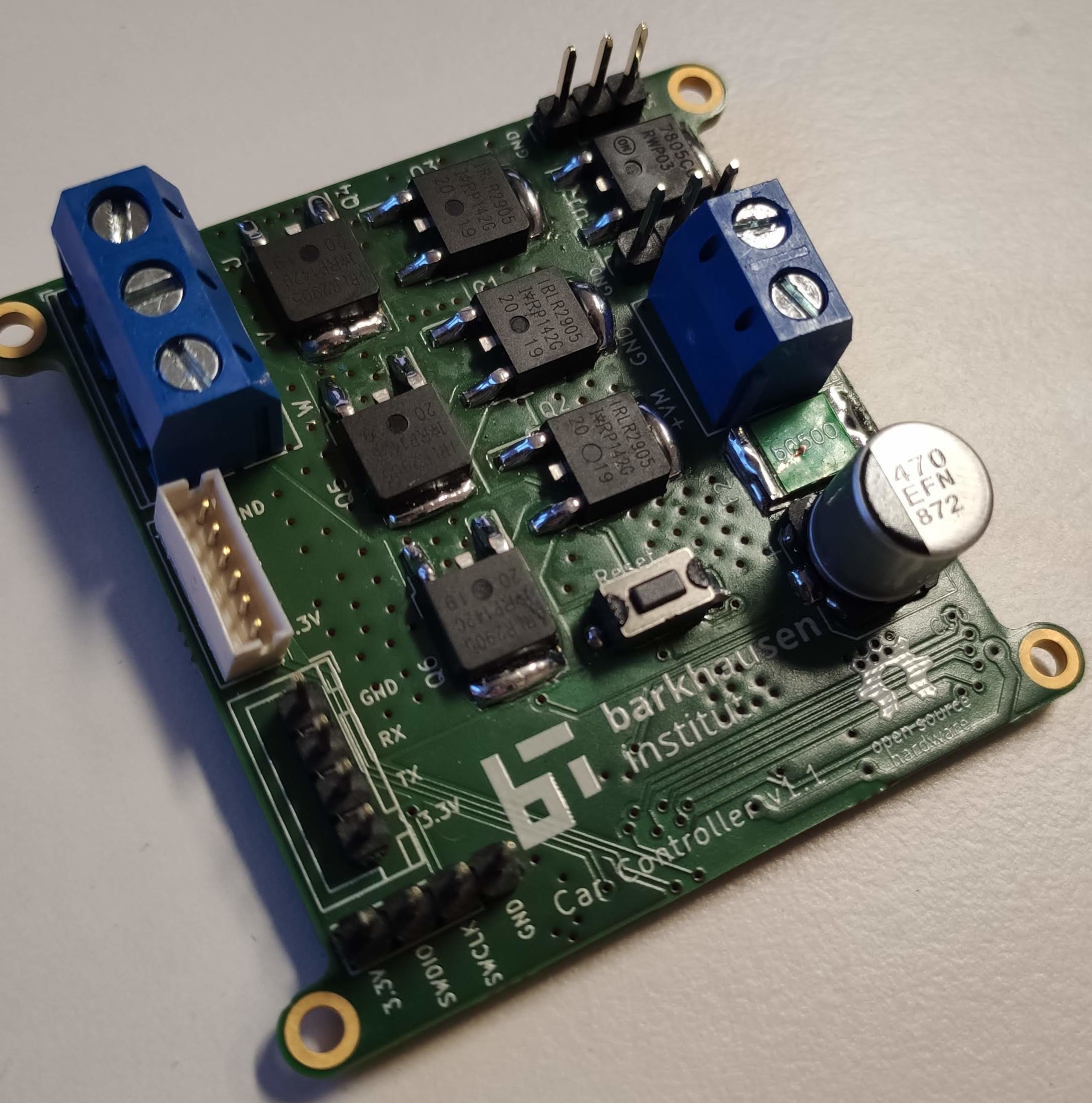
After these design changes new PCBs were ordered and assembled to test them again. And luckily this time everything worked as expected and the voltage spikes were a lot smaller so the STM didn't lock up.
The last part of the puzzle was to integrate the new motor controllers into our existing software. As we use ROS2 for the whole platooning demonstrator we needed to write an appropriate ROS2 node for interfacing with the motor controller. As stated earlier the motor controller is controlled over the serial interface of the STM32. This meant that we only needed to write a small node which gets control messages out of the ROS network and writes them to the serial interface as well as reads the feedback of the motor controller from the serial interface and publishes them to the ROS network. This then allowed us to completely control the motor controller from our existing software with just some minor changes.

Summary
Using existing open-source software and the right hardware we were able to create our own custom motor controller with all the features we needed for our specific use case and were able to open up our platform for more and different use cases thanks to better segmentation of software and hardware.
All our hardware design files, and software are on the following public Gitlab group